My recent order of boards from BatchPCB got lost somewhere on its way. I am not sure if it was lost by USPS, at customs or at my local post office here in Warsaw, but the fact is I am still waiting for a new memory and UARTs boards. BatchPCB is re-doing my order now at not extra cost, but it will take another 2 or 3 weeks for the boards to arrive. The IDE interface board which I ordered at a local fab house is not here neither, so I used the little spare time for a simple but important hardware tweak.
I implemented wait states logic in my clock generation circuit. Wait states are intentional delays in CPU/bus clock cycle introduced in order to allow more time for slow external devices to complete their work. Wait states are not necessary for a CPU to operate with devices, but without them the maximum clock rate is limited by the slowest device’s timing constraints. Until now, I was able to live without it but since I am about to build and test an IDE interface (which has quite rigorous timing characteristics) I decided to implement it. Otherwise, my maximum clock speed (currently at 4MHz) would have to be reduced quite significantly.
There are many ways to implement wait states. The most elegant approach would be to inhibit the clock whenever a slow device is accessed and let the device inform the CPU when it completed. In this scenario, wait states are device controlled. This way, wait states duration would be dependent on the accessed device type and speed and CPU time would be used most effectively. The drawback of this approach is increased circuit complexity (wait states logic has to be implemented for each peripheral).
Another way is to introduce uniform wait states into clock cycle controlled by the CPU. This is the approach I took. There is only one wait states circuit (in the CPU) and idleness duration is always the same. My CPU’s clock generation circuit is built using a simple Johnson counter generating two clock signals (one offset by quarter of a cycle with respect to another) at a quarter of the frequency of a generator. I described it a while back in this post. Call these signals Q0 and Q1 (generator signal is Q).

I am using the /IO signal generated by the memory module whenever device control memory range is accessed (addresses $1000-$1FFF). When this signal becomes active (indicating that a device is accessed) it is used to toggle a dedicated wait state JK flip-flop on a falling edge of Q1 to generate a stop signal that inhibits a clock. This is achieved by activating the /CLR input of a D flip-flop that forms a master clock generation Johnson counter. JK flip-flops holds this D flip-flop input low until next falling edge of Q1, effectively keeping the Qo and Q1 low for an entire extra cycle. The duty cycle of a modified clock in such case is 25% (75% of extended clock cycle is low) but since I am generating /ENMEM and /LDMEM signals during the low clock period, it is perfectly fine. You may think – how is the JK flip flop toggled out of the stop clock state, when there is no clock to unfreeze the system? That’s solved by adding a copy of a clock generation Johnson counter, which is non-maskable and is used only for controlling the wait state circuit and remains intact even if the stop clock signal is asserted. Please see updated schematics in the downloads section for details.
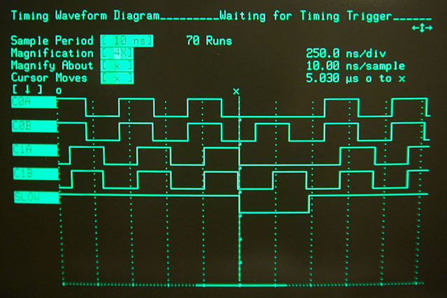
The screen from logic analyzer show how this works:

Signals C0A and C1A are master clock signals, whereas C0B and C1B are non-maskable clock. SLOW is the low active stop-clock signal which is generated by the JK flip-flow from a /IO signal on a falling edge of C1B. When this happens, both C0A and C1B are kept low for one full clock cycle until C1B (which remains operational at all times) toggles JK flip-flop again and brings the system back to normal operation. At 4MHz clock speed the low phase of the clock when wait state is introduced lasts 750ns which should be enough even for the slowest devices.
Dear Dawid
On this sam web site do you no Dieter Mueller I try to send a Email but the Email return have you got his email or how I can Contact him his project was the 6502